
Wireless Charging Weaknesses spur Innovation in Smartphone Industry
Jonathan Ive, the designer of the original iPhone, famously said in 2016 that “we believe in a wireless future”. There was clear intent from his employer in subsequent months to prove his statement true, as Apple joined the Wireless Power Consortium (WPC), the wireless charging standards body, the next year. Apple then launched the first iPhone with wireless charging capability and it also acquired a New Zealand-based wireless charging company called Power by Proxi which had more than 450 issued patents but zero consumer products.
However, Apple wasn’t a pioneer of wireless charging; instead, it was amongst the last major OEMs worldwide to adopt wireless charging. In fact, the long-forgotten Palm was the first to popularize a handset with integrated wireless charging in 2009. While Palm was quickly consigned to the history books, it was Samsung and Motorola, among other major OEMs, who widely adopted wireless charging starting in 2011.
For wireless charging to be relevant in the long term and to co-exist with the computer in our pockets, it needs to be safe, quick, ubiquitous, efficient, easy, cool, and cheap. This article will address some of these parameters with a focus on the materials and mechanisms that will be needed to make this happen. Subsequent research articles will unpack these parameters in more detail.
Power in a Smartphone
The inclusion of wireless charging has resulted in hardware challenges and opportunities for power management in smartphones.
Power management is an active innovation area and will always be such. This innovation spike is seen in solar power cells, battery management systems, electric vehicles, and smartphones. With the slow but steady surge of 5G adoption, the increased use of video conferencing applications, and the inclusion of a range of sensors and applications that drive the power-hungry computations in the CPU, GPU, Neural Engines, etc., optimized power performance is critical to enable high-quality consumer experiences.
The power network in a smartphone is a carefully designed system that needs to consider multiple peripherals as seen below.

The figure indicates the various blocks within an exemplary smartphone. Amongst these blocks, the most power-hungry are the display, the RF chipset, and the digital and analog basebands. Power to all the blocks is provided by the battery lines shown on the top and bottom. The battery is in turn fed by the charger (lower right corner in the image), which can be wired or wireless.
Let’s take another view of the power delivery network within the smartphone shown in the figure below.

The key takeaway from Figure 2 is that before power is delivered to any peripheral (such as a display or a camera), there are components that must condition the voltage. If all of the components ran at 3.7V (the same as the battery), then no conditioning would be required, however, that is not a reality. Conditioning is required, for example, for the audio codec, which runs at 1.8V, to use current from the 3.7V battery. Generally, the more conditioning the components required, the more energy is lost to heat. It is common for many components within a device to require a customized source voltage, so we expect there will be heat losses.
Wireless Charging
Having described a high-level view of an exemplary smartphone’s power network, we can now look at how a wireless charging system integrates with it.
Wireless charging utilizes magnetic fields to transfer energy from a transmitter coil in the charger to a receiver coil in a smartphone, as depicted in the below figure.

To enable this wireless energy transfer, multiple “conditionings” need to be performed to the power signal, all of which cause energy loss and lead to heat generation. Consider the below figure which describes the power conditioning and transmission path from the power supply to the battery.

Power Conditioning and Transmission Path
The leftmost block is connected via a cable to a power source (it can be a wall outlet or a portable battery). Each of the blocks loses energy as heat, the largest loss occurring at the transmitting and receiving coils. In addition to these stages, heat is generated in the materials of the phone and the charger itself. The figure below illustrates some key materials that will heat either directly due to the induction of eddy currents, or indirectly due to contact with materials that get hot.

The heating of materials and the phone body can lead to injury if not properly dissipated, In addition, the heating of some materials in the smartphone can lead to deleterious effects on the performance and lifetime of components such as the batteries.
Key Parameters for Wireless Charging
The key performance parameters of a wireless charging system were briefly mentioned in the introduction and are described in greater detail in this section. While the parameters are correlated, it is advised that each parameter should be measured or assessed independently.
Safe: As we move towards higher charging speeds (20W), it will be become increasingly difficult to ensure that the charger and device are thermally safe to the human touch. In addition, the heat emissions due to the switching inverters (on the T transmitter side and the rectifiers (on the receiver side) will also be higher, leading to additional product safety and compatibility challenges.
Quick: With larger batteries, the charging speeds also need to scale sufficiently to ensure consumer satisfaction. Designs need to ensure that the battery management systems (BMS), materials, manufacturing technologies, circuits, and coil designs are in lockstep with the battery roadmaps such as battery capacity and management technologies.
Ubiquitous: For increased awareness and usage of wireless charging, the ubiquity of chargers is required at various locations, for example at the home, office, and enterprises. Third-party transmitter chargers should be able to charge multiple smartphones and cross-compatibility is required. To enable compatibility, a standards body, the Wireless Power Consortium, was formed which develops the Qi protocol. The Qi protocol lays out the key rules for certain front-end hardware and portions of the software stack.
Easy: This refers to the convenience for the consumer in the entire charging experience. If a consumer must struggle with the physical placement of their device for effectiveness, the user experience is poor. Charging mats with large alignment areas that allow some tolerance in placement is far preferable.
Efficient: How many watts of power is being lost (as heat) when delivering 15W power to the battery? For an 80% efficient system, 3W is being lost. For a single handset, this may not be significant; however, when multiplied by the projected number of devices that will be using wireless charging, this becomes a significant number. This loss of efficiency leads to a slower charge speed and generates heat.
Cool: Keeping the device cool is a top priority for wireless charging. In some cases, lower efficiency may be acceptable, but we have to consider two questions: are the internal electronics and other hardware pieces getting so hot that their functionality is being affected, or worse, is the system getting too hot to the human touch?
Inexpensive: In the end, wireless charging is largely a convenience feature in most consumer electronics such as smartphones. For it to gain traction with consumers, it needs to make financial sense for the enterprises that install chargers in business establishments such as offices, restaurants, and for the consumers who buy standalone chargers and furniture pieces that have wireless chargers integrated into them.
Many electronics and product companies are embracing wireless charging. These companies include automotive OEMs for in-vehicle wireless charging (not EV charging), restaurants, aftermarket, and lifestyle product manufacturers such as Belkin, Mophie, Otterbox, and Popsockets. The architecture needed to achieve higher power levels in compact form-factors creates strong demands on every aspect of the product design, including the industrial design, the material stack up, material type and size, and the component selection.
This wave of new technology pushes companies to provide high value and longevity to the device's battery components, especially when those devices are exposed to third-party chargers. What kind of shielding is implemented to protect your device? And what are other sources of heat which reduce power efficiency? We can answer these questions by observing common wireless charging configurations, such as the Qi standard proposed by WPC.
The Standards
The Qi protocol, developed by the WPC, consisting of over 600 companies, describes the operation of a wireless charging system using a near-field magnetic coupling, which is also called induction coupling or magnetic coupling. The Qi-protocol clearly defines the process by which a device (e.g. a smartphone) will identify itself to a charger before the charger starts supplying wireless power. The key functional blocks of the system are represented in the figure below from the WPC website. The power receiver has been marked as the mobile device (smartphone) while the base station is the term used for a wireless charger.

As we discussed earlier in this article, wireless chargers are less efficient when compared to wired chargers. The presence of an air gap is one cause of losses, as do eddy currents. Materials that produce heat can also result in poor power efficiency. Heat reduces battery life, which is why designing for thermal protection warrants attention. How are devices being designed today to protect against a new, growing standard of charging?
The device’s battery, typically Li-ion-based, is considered to operate safely within a certain temperature range. Based on certain considerations stemming from battery safety, the industry has generally accepted a maximum temperature of a device when in contact with human skin to be about 45 C.
Fast charging is pushing power expectations higher, but manufacturers cannot simply scale up the same design to achieve higher wattage delivery. If a system delivered 5W with 1.5W of heat, then the same design at 10W could dissipate 3W of heat. This may cause performance issues such as bloating, corrosion, or other damage if the surrounding circuitry is not equipped to handle these conditions. Therefore, new designs must either reduce generated heat or dissipate the heat in a way that avoids localizing it.
Wireless Charging Hardware Stack – Shielding
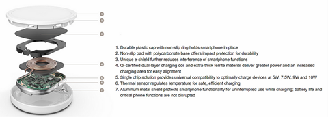
Shielding protects electronic components from undesirable electric and magnetic fields. In wireless charging applications, there is a desired magnetic field, but other fields must be redirected away from sensitive components. The image below from Apple shows the wireless charging material stack from their latest iPhone, the iPhone 12.

Wireless Charging Material Stack of iPhone 12 (Apple)
While this image is from a specific product, many smartphones have a similar stack. The most common shields used across smartphones are the copper-graphite shield and the nanocrystalline ferrite shield. The purpose of the graphite shield is to evenly spread the heat generated by the charging coil across a large surface area, while the purpose of the ferrite shield is to maximize the magnetic field coupling the charging coil, while also minimizing the magnetic field penetration into the phone body.
The below image describes a similar material blow up for a typical charger device:
The latest Qi documentation recently suggested relaxed shielding requirements and we now know that shielding is optional as long the device can be certified.
Commonly used types of shielding are metallic (Cu, Al, Steel) or ferritic (NiZn, MnZn, and other materials). As seen in the figure below, the receiver configuration places a layer of shielding to separate the phone circuitry from the power circuitry.
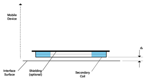
The Qi standards documentation recommends a soft ferrite shielding and suggests a specific placement and thickness. Ferrite materials provide magnetic shielding performance similar to other commonly used high permeability metals but have lower intrinsic magnetic noise generated by thermal Johnson currents due to their high electrical resistivity. [Reference 1]
It is interesting to note that while the Qi documentation contains over 40 different configurations for power transmitters, there are only five receiver configurations, each corresponding to a wattage level ranging from 5W – 15W.
Permanent Magnets
The Qi standard discourages the use of permanent magnets in the active area of devices. In-fact, it has deprecated some standardized transmitter coils that had permanent magnets. The purpose of such magnets was to ensure that the device is always aligned to the charger by the magnet’s attractive force. A major downside of these magnets was that they reduced the efficiency of wireless power transfer thereby nullifying any benefit due to better alignment. The WPC clearly mentions this in its specification, as quoted below from the Qi documentation.
(Qi Part 4: Reference Designs offers a further explanation of permanent magnets and power receivers/transmitters here: “NOTE: Power Receivers that use thin magnetic Shielding have been found to experience reduced performance on Power Transmitters that contain a permanent magnet in or near the Active Area. Such Power Receivers may exhibit, for example, less positioning freedom and/or a longer charging time. The remaining Power Transmitter designs provided in this part 4 of the Qi Power Class 0 Specification do not use a permanent magnet. Product implementations based on these designs that include a permanent magnet in or near the Active Area are not compliant with this specification.”)
Some permanent magnets are alnico, samarium cobalt, ferrite and neodymium. They usually increase the cost of devices, so finding a design solution without them makes sense economically but, if the design does include these permanent magnets in the active area, then it may not be Qi compliant.
However, as can be seen in the image of the iPhone 12, Apple has introduced permanent magnets as part of the solution at the receiver side, and possibly at the transmitter side as well. It is assumed that by ensuring good alignment through this innovative solution, the MagSafe, that the iPhone 12 will be able to charge at up to 15W with some chargers. Whether this works as expected and whether or not the addition of the magnets leads to a worse performance with installed transmitters in the infrastructure (as opposed to Apple-certified MagSafe-type transmitters) remains to be seen.
Ferrite Properties
The WPC Qi documentation makes two ferrite suggestions for the shielding components: nickel-zinc (Ni-Zn) and manganese-zinc (Mn-Zn). Mn-Zn ferrites are a class of soft magnetic materials that have very good electrical, magnetic and optical properties. The properties of Mn-Zn ferrites include high values of resistivity, permeability, permittivity, saturation magnetization, coercivity, and low power loss which makes them ideal for shielding applications.
Mn-Zn ferrites are preferred as they have higher permeability and saturation magnetization as compared to Ni-Zn ferrites. Because of the low-value resistivity of Mn-Zn ferrites as compared to Ni-Zn ferrites, these ferrites are used for low-frequency applications. Therefore, choosing a design between the Mn-Zn or Ni-Zn shield may be dependent on the frequency of operation.
Case Study: AirPower
In 2019, Apple's highly anticipated AirPower charging mat was canceled because the device did not meet the company's internal hardware standards. TechCrunch's Matthew Panzarino elaborated on AirPower’s cancellation:
"Everything I've personally heard (Apple is saying nothing officially) about the AirPower delay has been related to tough engineering problems related to the laws of physics. Specifically, I've heard that they ran too hot because the 3D charging coils in close proximity to one another required very, very cautious power management." The AirPower mat reportedly contained 22 charging coils, so that a user could freely place multiple devices anywhere on the mat. Besides creating heat, a high number of coils introduces other problems such as a complicated network of eddy current interactions. Eddy currents are unwanted currents generated in a conductive material because of magnetic fields. With reference to the schematic below, when the current in Transmitter Coil 1 generates a current in the receiver coil it is a “desired” current. However, when a current is generated in another transmitter coil due to interaction with the same magnetic field, that is called an “undesired eddy current.” This is illustrated in the figure below.

Undesired Eddy Current (Dr. Vinit Singh - Lumenci)
It will be interesting to see if Apple overcomes the issues with the AirPower mat and relaunches a similar product in the future. As of today, the focus appears to have shifted to a MagSafe type wireless connector, which is tightly coupled using magnets and enables a higher rate of charging (almost 2x the usual Qi charging) with Apple-branded transmitters.
The history of wireless charging design shows that the materials used change frequently depending on industry standards such as Qi or consumer demands such as Apple’s charging pad. The material chosen for devices can be both an aesthetic and practical decision. A glass-backed phone or glass-plated charging pad may seem like only an aesthetic choice at first glance, but as seen above, a glass backing can provide better wireless charging efficiency. If power efficiency standards become more strict on reducing waste, the choice to include materials like glass or shielding, which maximize power conversion efficiency and increase device longevity, will be more common.
The Future of Intellectual Property in Wireless Charging Patent publishing for this industry experienced a slow rise between 2014 and 2019. Since then, we’ve seen a sharp decline in publications as can be seen in the figure below. In February 2021, Samsung holds the most wireless charging patents at 890, more than three times that of the next competitor, LG Electronics. New batteries will enter the market, but it’s likely that Samsung will continue to lead the way in wireless charging improvements for now, partly because the wireless charging technology will not fundamentally change.

Leading Companies with Patents related to Wireless Charging Technology

Yearly Trend of Patent Applications related to Wireless Charging Technology
In summary, the data shows that activity in this sector is slowing. Samsung appears to have a competitive edge since they hold a large majority of wireless charging-related patents. Since patent publishing is trending downward, we may see more activity in patent monetization from existing publications instead.
*Disclaimer: This report is based on information that is publicly available and is considered to be reliable. However, Lumenci cannot be held responsible for the accuracy or reliability of this data.
*Disclaimer: This report is based on information that is publicly available and is considered to be reliable. However, Lumenci cannot be held responsible for the accuracy or reliability of this data.
Lumenci's Technology Team is developing a deep-dive analysis of the wireless charging industry that will cover the critical topics related to the Technology, Product Roadmap, Licensing, IP landscape covering the key players and Tech areas, and M&A Dealflow in the industry. Watch this space to know more.