
Optical Transceivers: Technical and IP Perspectives
Optical communication systems generally include three main active components- a transmitter (Tx), an optical fiber, and a receiver (Rx). A transmitter is a device that enables launching an electrical signal into an optical waveguide. Optical fiber is the optical waveguide that conducts an optical signal. The receiver is a device that enables the extraction of information from the optical fiber in the desired format. The transmitter has a light source and associated electronic circuits. The receiver has a light detector (e.g., photodiode) and associated electronic circuits.
In today’s technology, optical communication systems are primarily characterized using three dimensions: space (or length), time (or bit rate) and frequency (spectrum in the terahertz range). As an example, optical communications occurring in space can stretch to several kilometers (and even in tens of thousands of kilometers in intercontinental links). With respect to bit rates, long-distance (i.e., intercontinental) optical networks operate at the terabits per second (Tb/s) rate while metro optical networks (e.g., high-speed cable/internet) operate at hundreds of gigabits per second (Gb/s).
In modern optical communication networks, the presence of an optical transceiver module is more common. An optical transceiver module is an integrated circuit (IC) that can transmit and receive data in both directions independently. The optical transceiver module combines the transmitter and receiver of a conventional optical communication system into a single module. This facilitates converting electrical signals into optical signals to allow such signals to be efficiently transferred on fiber-optic cables.
With the inception of optical transceiver modules in the early 2000s, there are now several variants in the market. At a data rate of 1 Gbps, variations such as Gigabit Interface Converter (GBIC), Small Form-factor Pluggable (SFP), etc. are more common. While at a data rate of 10 Gbps, Enhanced Small Form-factor Pluggable (SFP+), C Form-factor Pluggable (CFP), etc. are widely used. QSFP+, QSFP28 and QSFP-DD are some variants of the Quad Small Form-factor Pluggable transceivers that are common for a data rate in the range of 40 to 400 Gbps. An interesting aspect to note here is many manufacturers of pluggable optical transceivers make their package compliant with multi-source agreement (MSA) – an agreement between multiple manufacturers to make products compatible across vendors and thereby establish a competitive market for interoperable products.
In addition, there are two main categories of optical transceivers: single-mode and multimode transceivers. Factors such as distance, cost and speed determine the choice between these two categories. As an example, single-mode transceivers are about twice or thrice the price of multimode transceivers. In telecommunication applications, a single-mode transceiver supports both higher data rates and a longer distance of transmission due to its low attenuation. In contrast, both single-mode and multimode transceivers are used in data communication applications at speeds as high as 400 Gbps.
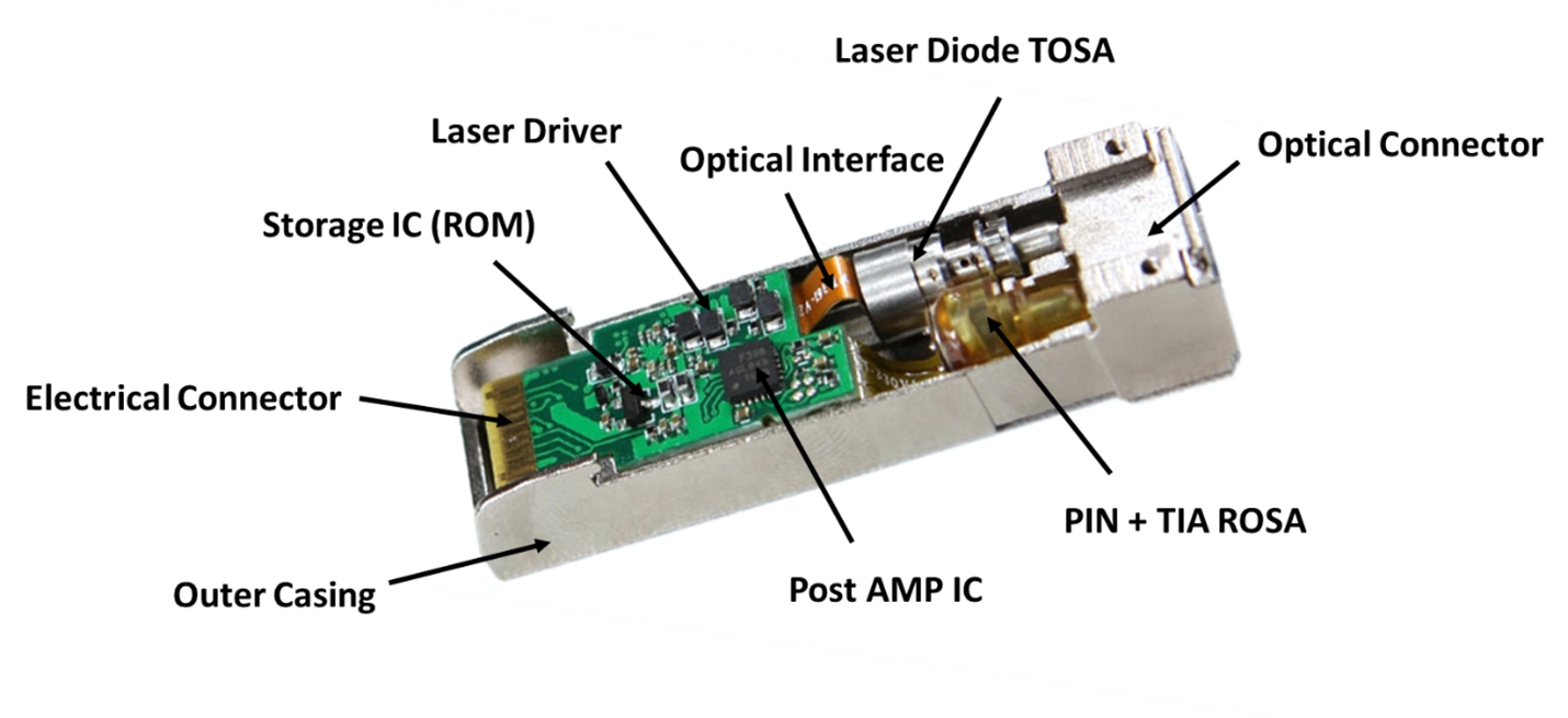
Product Teardown Image of an Optical Transceiver
The main components of an optical transceiver include an electrical input interface, an array of laser drivers, an array of light emitters, an optical multiplexer, an optical output connector, an optical input connector, an optical de-multiplexer, an array of light detectors, an array of trans-impedance amplifiers (TIA) and an electrical output interface. It is typical for a 100G QSFP28 transceiver to have both the electrical input interface and the electrical output interface include a 4x25G CAUI-4 electrical interface which is basically a four-lane chip-to-module and chip-to-chip electrical specification compliant with IEEE 802.3bm standard for Ethernet.
The product teardown image of an exemplary optical transceiver shown above helps to identify the important components inside the metal outer casing of the optical transceiver. At one end is an electrical connector and at the other end is an optical connector. The electrical connector is connected to a printed circuit board that includes an array of integrated circuit (IC) chips such as a laser driver, a storage chip (e.g., ROM), and a generic amplifier chip (shown as Post AMP IC). In addition, there is a transmitter optical subassembly (TOSA) at the transmit side, which includes a metal housing that contains a laser diode and an optical interface bus. In this example, the laser diode is a VCSEL operating at a central wavelength of 850 nm, which receives the driving current from the laser driver. A vertical-cavity surface-emitting laser (VCSEL) is a semiconductor-based laser diode that emits a highly efficient optical beam vertically from its top surface. The receiver side of the optical transceiver has a receiver optical sub-assembly (ROSA), which includes a plastic housing (seen in yellow). The ROSA includes a PIN photodiode, a trans-impedance amplifier (TIA), and an electrical interface. The storage IC appears to be a generic chip (ROM) that can be used to store information such as clock data in the electrical input signal.

In this report, we have chosen to compare a 100G QSFP28 SWDM4 pluggable optical transceiver manufactured by Finisar with a 100G QSFP28 BiDi transceiver manufactured by Broadcom. Note that the Finisar pluggable optical transceiver compared here is based on shortwave wavelength division multiplexing (SWDM) technology that makes use of multiple lasers called VCSEL’s that operate at different wavelengths in the 850nm window. The term SWDM4 stands for implementation using four wavelengths which are controlled individually by an array of VCSEL drivers. Each of the four wavelengths can operate at either 10G or 25G and thus allows the optical transceiver to perform optical transmission at either 40G (4x10G) or 100G (4x25G) in accordance with instructions from a 4:1 multiplexer. Both the optical input and output connectors use standard Duplex LC receptacles. On the other hand, a 1:4 optical de-multiplexer receives optical signals through an LC connector and communicates the optical input signals to an array of four PIN photodetectors (or photodiodes). The output from the photodetectors is received by an array of transimpedance amplifier (TIA) which amplifies the current output from the array of photodetectors. The TIA generates an electrical output signal which exits the optical transceiver through the electrical output interface.
The first notable difference between the two optical transceivers compared here is the direction of propagation of the optical interface. While Broadcom’s optical transceiver includes a dual wavelength VCSEL (2x50G) based bi-directional (implying Tx and Rx on both fibers) optical interface, Finisar’s optical transceiver includes a quad wavelength VCSEL (4x25G) based codirectional (implying separate Tx and Rx fibers) optical interface.
The second major difference is the type of modulation performed by the two optical transceivers. Note that Broadcom’s 100G BiDi optical transceiver uses pulse amplitude modulation 4-level (PAM4) while Finisar’s 100G QSFP28 SWDM4 uses non-return-to-zero (NRZ) (also called as PAM2). PAM4 is a multilevel signal modulation format for transmitting signals. Each signal level can represent 2 bits of logic information (e.g., 00, 01, 11, 10). In contrast, NRZ is a dual-level (high and low) signal modulation format for transmitting signals. The major advantage of PAM4 modulation over NRZ modulation is the ability to pull twice the signal (e.g., 50G vs. 25G for the two optical transceivers compared here). However, PAM4 modulation suffers from higher reflections when compared to NRZ modulation. In our comparison, Broadcom’s 100G BiDi optical transceiver has a maximum receiver reflectance of -15 dB while this is only -12 dB for Finisar’s 100G QSFP28 SWDM4 optical transceiver.
With respect to IP trends in the U.S., there seems to be tough competition to be a leader in terms of the number of patents granted on inventions related to optical transceivers. As shown below, between 2001 and 2011, Finisar Corporation (now acquired by II-VI Incorporated) has received the most U.S. patent grants. Sumitomo Electric Industries Limited only obtained a quarter of the total number of U.S. patents granted to Finisar Corporation during the same time period. Other top players include Emcore Corporation, IBM Corporation, and Avago Technologies.
Interestingly, among the top five players, only one of them is a non-U.S.-based company with its headquarters located in Japan.

However, the IP trend seems to have changed after 2011. As shown below, Sumitomo Electric Industries Limited obtained the highest number of U.S. patent grants on inventions related to optical transceivers. Between Applied Optoelectronics and Fujitsu, there is a very small difference in the total number of U.S. patents granted. Other key players include Avago Technologies and NEC Corporation. Interestingly, Finisar Corporation with ninety U.S. grants, appeared in the tenth spot among the key players during this decade (2011-2021). A closer look at the patents filed by Finisar during this timeframe indicates that several patents granted cover practical applications of optical transceivers such as protocols for out-of-band communication (US8798457), upgrading operational firmware in an optical transceiver using an optical link (US8582974), host-equalized optical links (US10298330), etc. This indicates that Finisar’s patent filing strategy aims to selectively cover the broad practical applications of the optical transceivers which were developed in the previous decade. This trend is also likely attributed to the acquisition of Finisar by II-VI Incorporated.
With respect to geographical distribution, the trend in the U.S. patent grants has shifted to a majority (three out of five) of Japanese companies being among the top players.

Percentage of US Patents granted between 2011 and 2021 (Total Grants- 5298)
(Source: Google Patents)
In conclusion, the future of pluggable optical transceivers appears to be very promising, with more demand for higher bandwidth resulting from higher data and traffic volumes from cloud services, smartphones, UHD 4k/8k video streaming, social media apps, and ongoing implementation of the Internet of Things. As several Webscale companies seek faster transmission rates that allow them to deliver content efficiently, we can likely anticipate pluggable optical transceivers operating at or above 1 Terabit per second (Tbps) in the next five years. In addition, tough competition may persist between U.S. and Japanese companies to be the leader in U.S. patent grants.
For a detailed report with competitive analysis and technology evolution, please reach out to us at: contact@lumenci.com
*Disclaimer: This report is based on information that is publicly available and is considered to be reliable. However, Lumenci cannot be held responsible for the accuracy or reliability of this data.
*Disclaimer: This report is based on information that is publicly available and is considered to be reliable. However, Lumenci cannot be held responsible for the accuracy or reliability of this data.
AUTHOR
Editorial Team at Lumenci
Through Lumenci blogs and reports, we share important highlights from the latest technological advancements and provide an in-depth understanding of their Intellectual Property (IP). Our goal is to showcase the significance of IP in the ever-evolving world of technology.